Introduction
I recently began my journey into the world of embedded devices. My main goal is to get a foothold into reverse engineering embedded devices, focusing, for now, on ARM. There is a whole lot of possible software configurations, which could run on embedded devices, ranging from full-blown Linux systems to bare-metal binaries, running without any operating system.
Coincidence decided the setup I used to start in reversing embedded firmware. As it happend a friend of mine brought along a little microcontroller board, the STM32F103C8T6, he ordered in bluk. Then I found a nice beginner book, recently released, about developing on that board with GCC and FreeRTOS. Since FreeRTOS is, as far as it seems, a kind of popular operating system used in embedded devices, the setup was settled.
Setup
Warren Gay, the author of the mentioned book, released a git repo containing a preconfigured developement environment build around FreeRTOS, libopencm3 and the board.
To start a new project follow the prerequisites stated in the readme. Then just:
cd ./rtos
make -f Project.mk PROJECT=name
cd ./name
make
You will receive a main.bin, the first binary I am going to examine in the following posts. To understand how a binary is build (and linked) as well as about ARM assembly I will examine the source code and the binary in parallel.
IDA setup
You might want to start reading the following sections of this post und come back later to learn how to load the firmware into IDA.
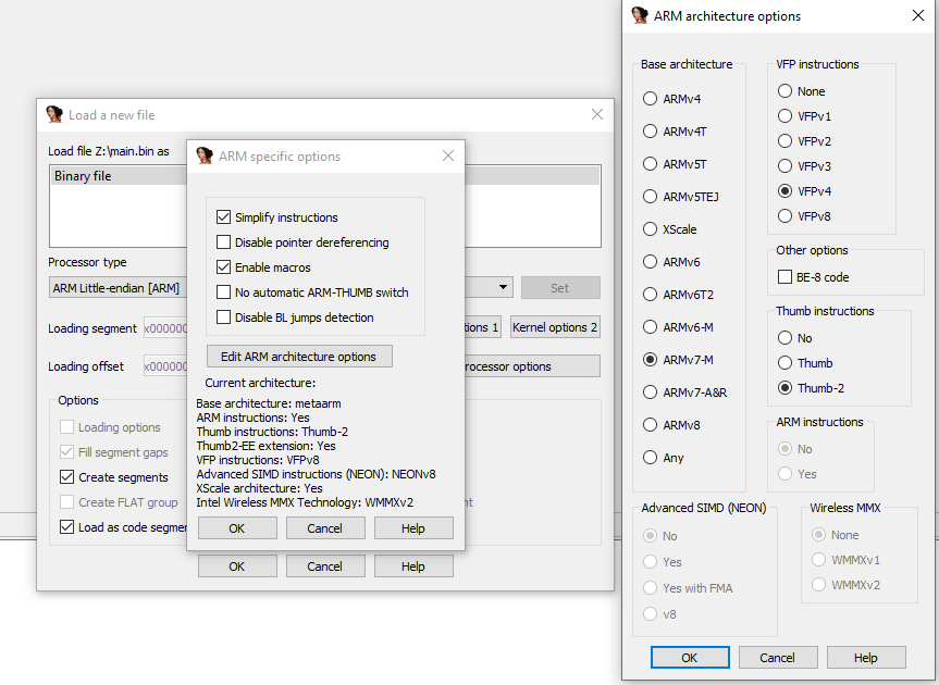
Start a new project, select ARM little endian as processor type and open the processor options. On the screenshots you can see the settings which worked for me. The Cortex-M3 has a ARMv7-M base architecture, so we set that.
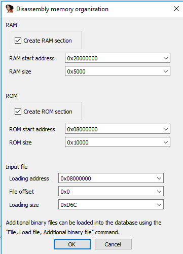
After confirming the settings IDA asks about RAM and ROM sections. You might wonder how to find the right values for these sections - thats part of the following sections.
In the main window IDA shows us the firmware but the code is not yet disassembled. To let IDA successfully disassemble our Code we need to enable Thumb mode: Alt+G: Enter 0x1 and confirm.
Next, set the values at 0x0800.0000 and 0x0800.0004 to Double-Words and jump to the value which appeared at 0x0800.0004: 0x0800.0CC5. Thats our entry point, the reset_handler (again, part the following enties of this series). Right-click and define "Code" at 0x0800.0CC4. I will explain in the following sections what just happend.
Now you should see the following picture:
You are ready to go.
STM32F103C8T6 boot and initialization
Where to start reverse engineering an embedded firmware image? Having a entry point is important - for example in in ELF binaries you can find the binaries entry in the ELF header. There might also be exports or even debug symbols. Each of that could be a starting point for reverse engineering an unknown binary.
In this firmware these entry points do not exist. As mentioned in the introduction, the starting point is a blob and a microcontroller, the blob is supposed to run on.
into the documentation
The first thing could be a look into the documentation of the microcontroller. In my case thats the STM32F103C8. Finding the right ressources might be in real-world scenarios more difficult. For the mentioned microcontroller nonetheless everything we need in the following sections is documented either in the programming or reference manuals you can find here.
memory layout
The microcontroller is able to boot either from the Flash, the embedded SRAM or the System Memory. Depending on the BOOT pin configuration the the adresses 0x0000.0000 to 0x0800.0000 are either aliased to the Flash or to the system memory regions.
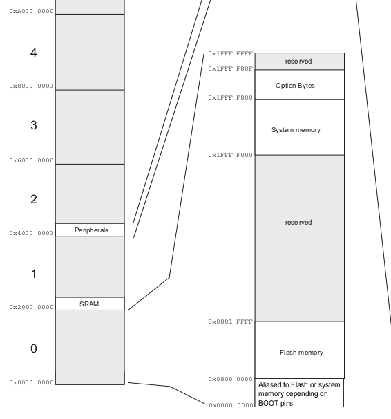
The important memory regions for now:
- System Memory: 0x1FFF.0000 to 0x1FFF.F800
- Flash Memory: 0x0800.0000 to 0x0801.FFFF
- SRAM at 0x2000.0000
vector table
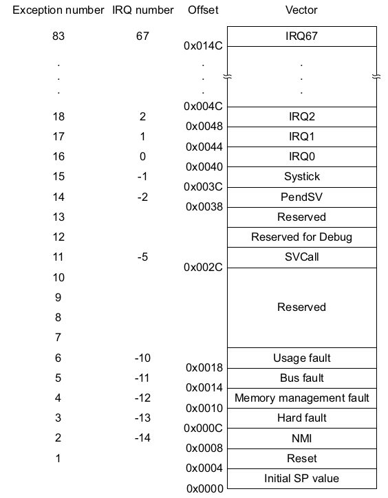
In the used cores, an ARM Cortex-M3, the boot process is build around the reset exception. At device boot or reboot the core assumes the vector table at 0x0000.0000. The vector table contains exception routines and the initial value of the stack pointer. There is a Vector table offset register (SCB_VTOR) where you can load a offset from 0x0000.0000 to relocate the vector table during runtime.
On power-on now the microcontroller first loads the initial stack pointer from 0x0000.0000 and then address of the reset vector (0x0000.0004) into the program counter register (R15). The execution continues at this address. As you can see in the following picture the reset vector is at 0x.0000.0004. The initial stack pointer value will be at 0x0000.0000.
into the binary

Marked blue and red we can see the mentioned memory regions:
- 0x2000.5000 is the initial stack pointer value, pointing into SRAM
- 0x0800.0CC5 the address of our reset routine, executed at power-on and reset of the embedded device. The fact that bit 0 is 1 indicates that the processor should start in Thumb mode (activate Thumb mode if PC bit 0 is 1). In the current case that is also clear by looking at die Cortex-M3 spec since these processors only support Thumb mode.
into the source
The project provides a liker script which defines the memory layout of our destination binary. Let's have a look how the binary we just looked at was build:
MEMORY
{
        rom (rx) : ORIGIN = 0x08000000, LENGTH = 64K
        ram (rwx) : ORIGIN = 0x20000000, LENGTH = 20K
 }

 /* Enforce emmition of the vector table. */
 EXTERN (vector_table)

 /* Define the entry point of the output file. */
 ENTRY(reset_handler)

 /* Define sections. */
 SECTIONS
 {
         .text : {
                 *(.vectors)     /* Vector table */
                 *(.text*)       /* Program code */
                 . = ALIGN(4);
                 *(.rodata*)     /* Read-only data */
                 . = ALIGN(4);
         } >rom
[...]
PROVIDE(_stack = ORIGIN(ram) + LENGTH(ram));
file: stm32f103c8t6.ld
The linker script first defines two memory sections with their permissions (read-write for rom and read-write-execute for ram). Then, in the sections defintions, we see the .text segment defined with the the different parts it consists of, especially the vector table which is placed at the beginning of the .text segment:
.text : {
                 *(.vectors)     /* Vector table */
                ...
                } > rom
This instructs the linker to include all sections named .vectors from all files (the *) into the text segment and put it into rom, which is defined in the MEMORY statement.
The vector table we reverse engineered from the firmware is defined in the vector.c file of libopencm3:
 __attribute__ ((section(".vectors")))
 vector_table_t vector_table = {
         .initial_sp_value = &_stack,
         .reset = reset_handler,
         .nmi = nmi_handler,
         .hard_fault = hard_fault_handler,

 /* Those are defined only on CM3 or CM4 */
 #if defined(__ARM_ARCH_7M__) || defined(__ARM_ARCH_7EM__)
         .memory_manage_fault = mem_manage_handler,
         .bus_fault = bus_fault_handler,
         .usage_fault = usage_fault_handler,
         .debug_monitor = debug_monitor_handler,
 #endif

         .sv_call = sv_call_handler,
         .pend_sv = pend_sv_handler,
         .systick = sys_tick_handler,
         .irq = {
                 IRQ_HANDLERS
         }
 };
file: stm32f103c8t6/libopencm3/lib/cm3/vector.c
That fits to the "reverse engineered" structure of the binary firmware: Bytes 4-7 is the reset_handler, which is the address of the function defined later in vector.c, and the first four bytes are the initial_sp_value. Since rom is defined to start at ORIGIN = 0x0800.0000, the reset routine is placed, exactly as encountered in the section "into the binary", within the address range (0x0800.000 + 64K. 64 * 1024: 0x1.0000 addressable bytes, means highest rom address: 0x0801.FFFF)
Then the initial stack pointer value is calculated by the linker based on the size of rom and ram, provided as _stack symbol, whose address is then included in the vector_table struct - and placed as the first 4 bytes of the firmware.
So we not only found the reset routine as a starting point to reverse engineer, we also know that the firmware of that device is supposed to boot from Flash memory. Remember: Either the Flash memory, starting at 0x0800.0000 or the SRAM, starting at 0x1FFF.0000, is mapped to 0x0000.0000.
I assume you could also link the firmware with roms value of ORIGIN as 0x0000.0000 since the memory regions 0x0800.0000 are aliased (with the according BOOT pin configuration). In that case the the boot source would not be obvious from the firmware.
libopencm3: calling main()
The reset_handler in libopencm3 is pretty simple. Nonetheless it shows pretty nice what has to be done before a user-supplied main()-function can be called.
As we already found out the initial entry point, the address which was located at 0x0000.0004, is 0x0800.0CC5. We start our reverse engineering there.
into the binary
This is now the point you should have a look at the introduction and especially how to set up IDA Pro.
.data and .bss initialization
Besides the .text section the linker script specifies the .bss and the .data section. .bss holds uninitialized, zeroed, .data the initialized variables.
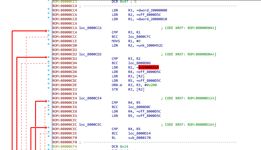
One fact we already found out by looking first at the documentation and then at the binary, is that RAM will start at 0x2000.0000. From the disassembly we could deduce the same:
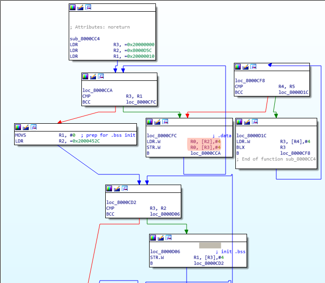
As shown in the the disassembly, first base address 0x2000.0000 is load into R3. Then 16 bytes (0x2000.0010 - 0x2000.0000, the CMP R3, R1), starting at 0x0800.0D5C, are copied to the address R3 points to. These 16 bytes form the .data section, the initialized variables. Remember the post-indexed ARM instructions (orange), which increment (in this case by 4) the second operand automatically after the operation STR/LDR is done. We can see the .data section in the binary firmware:

After that, appended to the .data section (R3 is incremented further), .bss follows. Since the .bss section holds undefined data initialized with zero, we can easily spot it: Starting at 0x2000.0010 up to 0x2000.452C, everything is initialized with 0. (R1 holds 0 and gets written to [R3])
.init_array
The next part of the reset_handler seems to be any kind of initialization array, which holds a list of function pointers. From the source we will learn that this is the .init_array
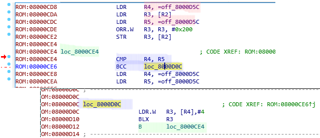
What the disassembly shows in a nutshell:
- Two values are compared (red). In this case they are the same - it seems like the linker did not find any values for the .init_array. Let us assume there were some entries in the array.
- If there would be some, the processor would jump to loc_8000D0C, load the next function pointer into R3 from R4. Update (post-index increment) then R4 (pointer into the array) by 4 to the next value.
- branch to the value in R3
- repeat until R4 == R5.
into the source
The reset_vector for the FreeRTOS firmware is compiled in from the libopencm3 library, which defines the vector in libopencm3/lib/cm3/vector.c:
void __attribute__ ((weak, naked)) reset_handler(void)
{
        volatile unsigned *src, *dest;
        funcp_t *fp;

        for (src = &_data_loadaddr, dest = &_data;
                dest < &_edata;
                src++, dest++) {
                *dest = *src;
        }

        while (dest < &_ebss) {
                *dest++ = 0;
        }
        [...]

        for (fp = &__preinit_array_start; fp < &__preinit_array_end; fp++) {
                (*fp)();
        }
        [...]

        main();
[...]
}
As already described first .data and .bss gets initialized. The _data_loadaddr and _ebss symbols are defined in the linker file, when the sections get defined:
.data : {
        _data = .;
        *(.data*)       /* Read-write initialized data */
        . = ALIGN(4);
        _edata = .;
} >ram AT >rom
_data_loadaddr = LOADADDR(.data);

.bss : {
        *(.bss*)        /* Read-write zero initialized data */
        *(COMMON)
        . = ALIGN(4);
        _ebss = .;
} >ram
main()
After the initialization of .bss, .data and calling all init functions main() gets called.
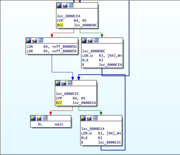
In that case it is pretty obivous which function is main(). I assume in some firmwares finding main() could be more difficult than that.
FreeRTOS: Finding Tasks
I am skipping the FreeRTOS intruduction since there are plenty of resources summarzing FreeRTOS to an extent which is sufficient to understanding the following. The most important part to know is that FreeRTOS consist of Tasks. These Tasks are user-written. Additionally there is one IDLE task which gets created by the system and is called when no user-written task is working.
As we do not really want to reverse engineer FreeRTOS itself but only the user-written tasks, I asked myself: how could I find only these?
I came up with two possible ways
searching for the xTaskCreate prototype
BaseType_t xTaskCreate( TaskFunction_t pxTaskCode,
  const char * const pcName,
  const configSTACK_DEPTH_TYPE usStackDepth,
  void * const pvParameters,
  UBaseType_t uxPriority,
  TaskHandle_t * const pxCreatedTask )
We can expect the following disassembly:
- R0 holds a address > than 0x0800.0000 (the function pointer of the task)
- R1 holds a pointer to a string. Can be in .data or in .text.
- R2 holds a integer
- R3 can be really anything
- two parameters on the stack: 5th: integer, 6th: NULL or an address (variable TaskHandle_t).
In my example, if we disassemble the found main() function, wie see:
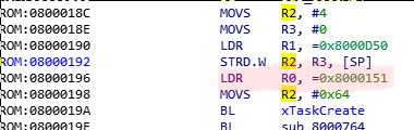
As mentioned when xTaskCreate is called R0 will hold a function pointer to the user-written address - exactly what we found in main(). (marked red).
searching the IDLE Tasks
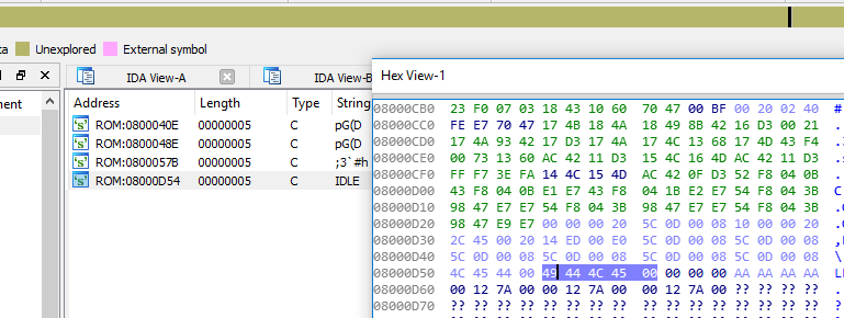
As I mentioned in the introduction, FreeRTOS automatically creates a IDLE task which is running in the background. For that task the second parameter (pcName) is, in the default setting, 'IDLE'. If luck is with the reverse engineer the engineers did not change the default name. In that case we find "IDLE" somewhere in the binary:
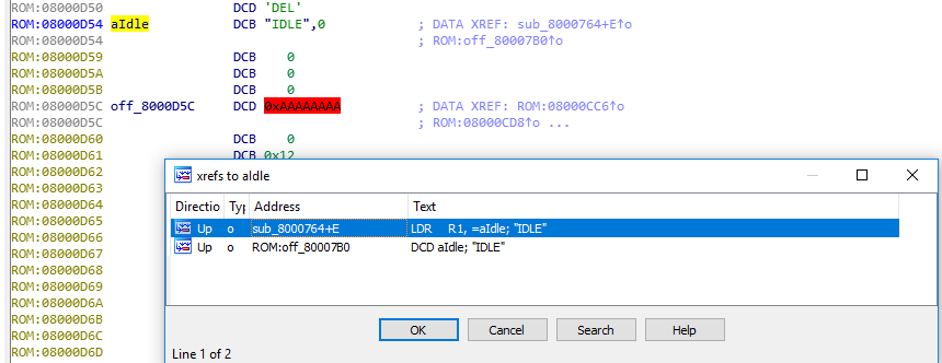
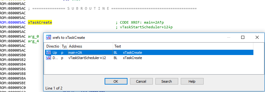
By cross-referencing that (CTRL-x) we find the place where the string is loaded:
The Idle-Task is created in the function vTaskStartScheduler. We already saw how a "xTaskCreate() call looks like in assembly. We can expect to find this prototype in xTaskStartScheduler, where xTaskCreate() is called for the IDLE task:
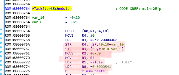
The IDLE task is located at 0x0800.0541. The stack and the registers get prepared with the mentioned values and then a branch with link is taken to xTaskCreate. By cross-referencing xTaskCreate we can find all user-implemented Tasks and start reversing them... But that will be (hopefully) part of another blog post :)
into the source
Now that's not really the most interesting part since the implemented Task is pretty boring. But for the sake of completeness the called main() function:
main(void) {

        gpio_setup();
        xTaskCreate(task1,"LED",100,NULL,configMAX_PRIORITIES-1,NULL);
        vTaskStartScheduler();
        for (;;)
                ;
        return 0;
}
rtos/projectname/main.cs